Assembly Procedure Using Paired Features
When paired features mode is employed, assembly applications have two process steps for each part: (1) Calibration and (2) Run time. During the assembly operation, vision system calculates the position differences between the two parts' features as if one part's position were the other's target pose, and calculates the necessary motion move that will minimize the error across all the paired features and provides the necessary feedback to the motion system.
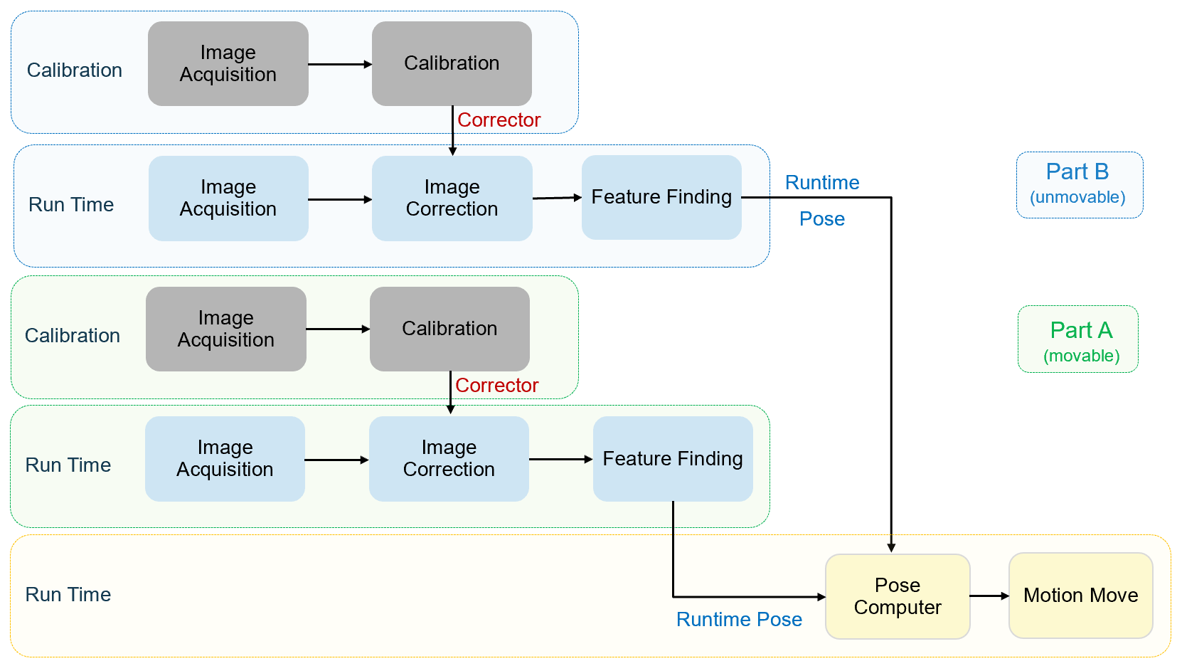
Calibration
During calibration, both stations run a separate calibration process first, then vision system unifies the two calibration results to create a shared coordinate space for all cameras and motion devices. This shared coordinate space is called Home2D.
After calibration, each camera will have a Corrector which saved the transform between its raw image coordinate space and Home2D space. These Correctors afterward will be used to correct train time and run time images.
Run Time
For the first time of run time tasks running, certain setups should be conducted to configure vision tools for both parts' feature finding:
1. Configure vision tools for Part A and Part B feature finding
2. Use the same feature names for every feature pairs from Part A and Part B so that run time pose computation will recognize them as pairs
3. Save the configurations above in alignment recipe.
After calibration and vision tools configuration, run time tasks are ready to be executed every time when vision system needs to guide motion for completing the assembly task. Run time has two procedures: feature finding and pose computing.
The steps of feature finding that two parts run separately are:
- Acquire image(s)
- Using image correctors from calibration data to transform raw images to corrected images
- Use vision tool to find the features on current part.
The steps of pose computing are:
- The vision system calculates the pose differences between two parts' paired features.
- The vision system computes the pose motion device should move based on calculated part pose difference and the mechanical way of part handling.
- Motion device move to an absolute pose (x,y,theta) or a relative pose(dx,dy,dtheta) provided by vision system from current or trained pose to align part A to fit Pat B.
Part B and Part A's feature finding tasks can run asynchronously. However, pose computing should be conducted only after both parts' features are found.
There are three different ways of part handling: